- 您现在的位置:买卖IC网 > Sheet目录3833 > AT87251G2D-3CSUM (Atmel)IC 8051 MCU 32K OTP 24MHZ 40DIP
25
AT/TSC8x251G2D
4135F–8051–11/06
4. If this instruction addresses external memory location, add 2(N+2) to the number of
states (N: number of wait states).
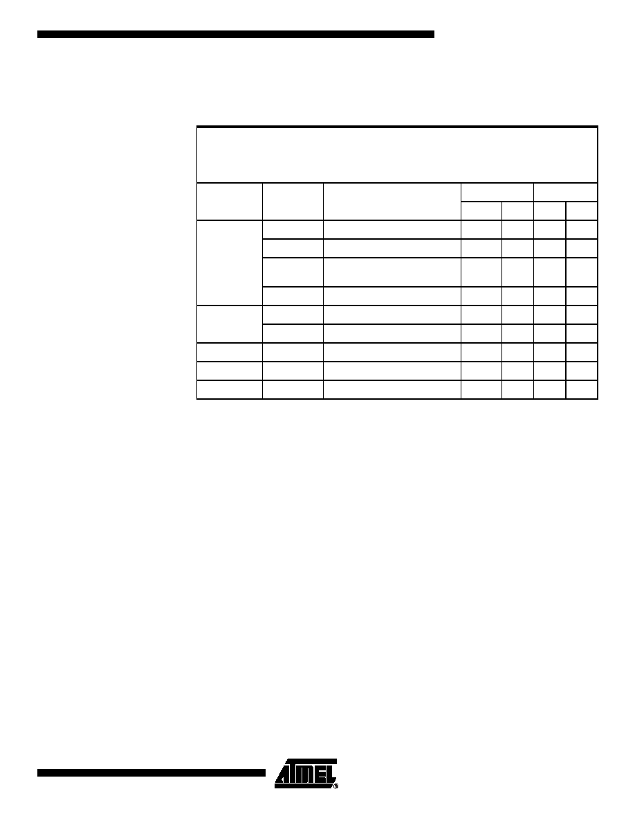
Table 21.
Summary of Increment and Decrement Instructions
Notes: 1. A shaded cell denotes an instruction in the C51 Architecture.
2. If this instruction addresses an I/O Port (Px, x = 0-3), add 2 to the number of states.
Add 3 if it addresses a Peripheral SFR.
IncrementINC <dest>dest opnd
← dest opnd + 1
IncrementINC <dest>, <src>dest opnd
← dest opnd + src opnd
DecrementDEC <dest>dest opnd
← dest opnd - 1
DecrementDEC <dest>, <src>dest opnd
← dest opnd - src opnd
Mnemonic
<dest>,
<src>
(1)
Comments
Binary Mode
Source Mode
Bytes
States
Bytes
States
INC
DEC
AACC by 1
1
Rn
Register by 1
1
2
dir8
Direct address (on-chip RAM or
SFR) by 1
22(2)
at Ri
Indirect address by 1
1
3
2
4
INC
DEC
Rm, #short
Byte register by 1, 2, or 4
3
2
1
WRj, #short
Word register by 1, 2, or 4
3
2
1
INC
DRk, #short
Double word register by 1, 2, or 4
3
4
2
3
DEC
DRk, #short
Double word register by 1, 2, or 4
3
5
2
4
INC
DPTR
Data pointer by 1
1
发布紧急采购,3分钟左右您将得到回复。
相关PDF资料
AT80C51RA2-SLSUM
IC 8051 MCU ROMLESS 44PLCC
AT80C51RA2-SLSUL
IC 8051 MCU ROMLESS 44PLCC
AT80C51RA2-RLTUM
IC 8051 MCU ROMLESS 44VQFP
213931-5
CONN JACKSCREW RECEPT 34 POS
AT80C51RA2-RLTUL
IC 8051 MCU ROMLESS 44VQFP
AT80C51RA2-3CSUM
IC 8051 MCU ROMLESS 40DIP
AT80C51RA2-3CSUL
IC 8051 MCU ROMLESS 40DIP
AT80C31X2-SLSUM
IC 8031 MCU ROMLESS 44PLCC
相关代理商/技术参数
AT87251G2D-RLTUL
制造商:ATMEL 制造商全称:ATMEL Corporation 功能描述:B/16-BIT MICROCONTROLLER WITH SERIAL COMMUNICATION INTERFACES
AT87251G2D-RLTUM
功能描述:8位微控制器 -MCU 251G2D 8/16bitC OTP 5V RoHS:否 制造商:Silicon Labs 核心:8051 处理器系列:C8051F39x 数据总线宽度:8 bit 最大时钟频率:50 MHz 程序存储器大小:16 KB 数据 RAM 大小:1 KB 片上 ADC:Yes 工作电源电压:1.8 V to 3.6 V 工作温度范围:- 40 C to + 105 C 封装 / 箱体:QFN-20 安装风格:SMD/SMT
AT87251G2D-SLSUL
功能描述:8位微控制器 -MCU Microcontroller
RoHS:否 制造商:Silicon Labs 核心:8051 处理器系列:C8051F39x 数据总线宽度:8 bit 最大时钟频率:50 MHz 程序存储器大小:16 KB 数据 RAM 大小:1 KB 片上 ADC:Yes 工作电源电压:1.8 V to 3.6 V 工作温度范围:- 40 C to + 105 C 封装 / 箱体:QFN-20 安装风格:SMD/SMT
AT87251G2D-SLSUM
功能描述:8位微控制器 -MCU OTP 8/16bit St 5V 24MHz RoHS:否 制造商:Silicon Labs 核心:8051 处理器系列:C8051F39x 数据总线宽度:8 bit 最大时钟频率:50 MHz 程序存储器大小:16 KB 数据 RAM 大小:1 KB 片上 ADC:Yes 工作电源电压:1.8 V to 3.6 V 工作温度范围:- 40 C to + 105 C 封装 / 箱体:QFN-20 安装风格:SMD/SMT
AT875
制造商:POSEICO 制造商全称:POSEICO 功能描述:PHASE CONTROL THYRISTOR
AT875LT
制造商:POSEICO 制造商全称:POSEICO 功能描述:PHASE CONTROL THYRISTOR
AT875LTS44
制造商:POSEICO 制造商全称:POSEICO 功能描述:PHASE CONTROL THYRISTOR
AT875S44
制造商:POSEICO 制造商全称:POSEICO 功能描述:PHASE CONTROL THYRISTOR